Better by December

At the end of 2022 I had scheduled vacation days, but plans fell through and I found myself with extra time to kill. I generally do better when I have something to keep me out of trouble, so I built a web application.

With the new year rapidly approaching I was starting to think about goals that I had for 2023 and how to track them. I again wanted to do 10,000 sit ups and 10,000 pushups over the year. Also, my Wife and I wanted to go on 150 walks together. In addition to goals, I also wanted track other things such as the books I read and the number of days I played guitar. The hope was by doing those things I’d be a better person by the next December.

For those who might be interested in the basic architecture, here’s a summary of the various pieces I built and/or assembled:

  • I have a “december-back” repository on Github (currently the repository is private) which does most of the work for the service. I wrote that in Golang.
  • I have a “december-front” repository on Github (currently the repository is private) which provides the web user interface for the service. I wrote that in JavaScript/TypeScript using React.
  • The “december-front” project is built using npm and the resulting artifacts are stored in an AWS S3 bucket and delivered via Cloudfront.
  • The “december-back” project is packaged into a Docker image and published to a registry via a Github action.
  • Docker containers are spun up in AWS ECS (Elastic Container Service) on Fargate.
  • Route53 on AWS takes care of domain registration for betterbydecember.com and also provides all the DNS goodness and ensures requests are correctly directed to the front or back end.
  • An EC2 Load Application Load Balancer can direct traffic to one of two different regions and also takes care of all the https certificate goodness.
  • All the data is stored in a DataStax Astra database since it’s “a database I want to use“.

The web app is available at https://www.betterbydecember.com/ and anybody can try it out. It’s been over a year since the basic functionality was complete and I started using it to track my progress. I met my 2023 goals and feel like I became Better by December. Now that 2024 is in full swing, I’ve set new goals and am actively working towards becoming Better by December.

A Database I Want to Use

If you’re only interested in connecting your ESP8266 to a database, skip to the bottom paragraph. If you’re not interested in databases, read the whole thing.

I am not interested in databases. As a software developer, I understand the value of a good database and I like using databases to store/retrieve/search/etc. data. The part I don’t like is the setting up, configuring, optimizing, scaling, maintaining, and other tasks required to keep a database up-and-running. I want to spend my time writing code rather than babysitting a database. I want to use a database, not run a database.

Nearly four years ago when playing with my then new ESP8266 I needed a database and I ended up going with REDIS and WEBDIS because it was the lowest bar to entry that I could find for my requirements. It has worked well-enough for my needs, but nothing to rave about. I’ve spent the past two years making something exponentially better.

In 2018 I joined Datastax which is the most important company behind the NoSQL database Apache Cassandra. Cassandra was not a database that I wanted to use. While the performance, scalability and reliability of Cassandra are unsurpassed, the complexity to get Cassandra ready to go and keep it running was a deal breaker for someone like me that isn’t interested in being a DB admin.

As a Senior Software Engineer on the Datastax Cloud Team I had various responsibilities, but my personal goal was to create a database I wanted to use. The team succeeded with Datastax Astra which is a “Cloud-native Database-as-a-Service built on Apache Cassandra”. That means I can just go to a website, fill in a few details, click a button, and seconds later I have a database I can use. It’s awesome.

My day job was working to make Datastax Astra a database I wanted to use and finally I am able to spend my weekends using it. I created an Arduino library called astra_esp8266 which makes it easy for an ESP8266 to communicate with a database. The source code is available on github but most users will probably just want to install the library into an Arduino IDE. After four years, with two of those years taking thousands of hours of my time, there is now a database that I want to use.

Meeting Time

My home is typically not quiet. Lately, with everyone home, it means there’s been even more noise. The kids are supposed to practice their various instruments daily which include piano, saxophone, trombone, and clarinet (not to mention the “bonus” ukulele and drum playing). Boy#2 is on a smoothie kick when means the blender is frequently running. Doors slam as kids run out to play in the yard and then come back in yelling about minor injuries. Conversations (calm and animated) abound.

A year or two ago I purchased an “On Air” sign online. The cord exited from the side so I modified it so instead the cord sticks straight out the back. It was intended to be hung by a chain (included), so I added some slots to be able to screw it directly to the wall. I then removed the plug and pushed the cord through a hole I drilled in the wall. The cord was rewired to an extension cord that plugs in to a simple “smart” plug. From there it was simple to hook it into our Alexa home ecosystem.

Now, when I have a meeting and need the house to be quieter-than-normal, I just say “Alexa, turn on broadcasting” (saying “turn on on air” sounded awkward to me) and the sign illuminates. But beyond that, my family is good enough to recognize the glowing red above my door and refrain from high audio behaviors.

Configuring a Raspberry Pi from Another Computer

Introduction

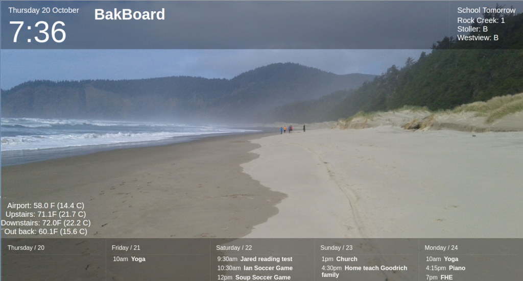
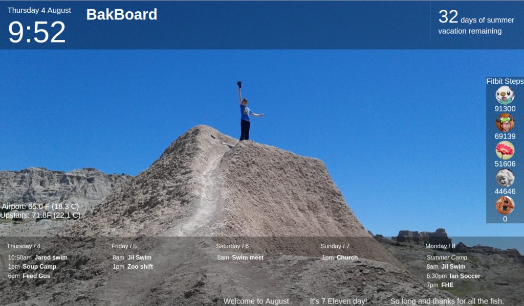
One thing I like about the Raspberry Pi is that it’s a small gadget that, once configured, only needs power in order to sit somewhere and do something.  For example, BakBoard runs on a Raspberry Pi that only plugs into a TV (for both power and display).  Unfortunately, in order to get everything running, I typically have ended up connecting various extra wires (network, keyboard, mouse, display) and work directly on the Pi before I can stick it in some random location to do what I want it to do.  Below are the steps I figured out so that I can do everything from my main computer and the only wire I need to my Pi is for power.

Prereqs

  • My main computer is currently running Ubuntu 16.04 although I think it would be easy to adapt the steps for most operating systems.
  • I have an SD card (32 GB in my case, but it probably only needs to be about 4GB).
  • I have an SD card adapter so I can read/write the SD card from my computer.

OS Image

To get the base image, I went to the Raspberry Pi Downloads Page and grabbed the latest Raspbian image (specifically 2017-01-11-raspbian-jessie-lite).  Once I had downloaded the zip, I opened it and then doubled clicked the image file (2017-01-11-raspbian-jessie-lite.img).  This brought up the Ubuntu image tool and it was easy to “restore” the image to the SD Card.

Wireless Networking

Since I don’t want to mess with a network cable, I want my Pi to be able to access my wireless network.  In order to do so, I modified the interfaces file.  It is in the image at etc/network/images.  Basically I changed the bit:

iface wlan0 inet manual
    wpa-conf /etc/wpa_supplicant/wpa_supplicant.conf

To be:

iface wlan0 inet dhcp
    wpa-ssid "NATHANS_NETWORK"
    wpa-psk "NATHANS_PASSWORD"

Obviously I plugged in the correct network name and password.

Enable SSH

The Raspbian OS used to have SSH enabled by default, but last year that changed as a security precaution.  The explanation for the change (and where I learned to do what is described below) is described on the Raspberry Pi Blog.

Basically, to enable ssh, I just create a file called “ssh” in the boot directory.  The contents of boot/ssh don’t matter–apparently the OS will see that file, enable ssh, and then delete the file.  The tricky part was that there were two “boot” directories.  There was one at the root of the volume, but there was actually a separate volume as well that is named boot–that’s the one where the ssh file must be created.

Authentication

The default password to  the Raspberry Pi is well-known which is nice because I don’t have to remember yet another password, but also a security risk since everyone knows it.  Instead, I like to use key based authentication and disable password authentication for ssh access.  Here’s how I did that:

First, I generated my public and private key (that was done a long time ago, and there are plenty of sources on the Internet how to do that).  My public key is id_rsa.pub (in the .ssh folder in my home directory) and the private key is id_rsa.  That creation was on my main computer.  Then, on the Raspberry Pi volume, I created the directory home/pi/.ssh.  I then copied the public key file (id_rsa.pub) into the home/pi/.ssh folder and also copied the file and named the copy “authorized_keys”.

Then, to disable password authentication via SSH I opened up the file etc/ssh/sshd_config in a text editor and changed:

#PasswordAuthentication yes

UsePAM yes

To be:

PasswordAuthentication no

UsePAM no

Conclusion

Once the above has been completed, I can stick the SD card into the Raspberry Pi and then plug in the Pi (giving it power).  It automatically connects to the wifi and I’m able to SSH into it without a password.  There’s nothing new here that can’t be found in various places online, but I’ve gathered the pieces together for my own reference at least.  Here are a few “gotchas” I encountered along the way:

  • All of the paths mentioned above are relative paths–the volume might be mounted in various places–in my place it was something like /media/nathan/90asd8f60s9g69789sd6gjherlkuyds8 for the main volume and /media/nathan/boot for the boot volume.
  • As mentioned before, there are two “boot” directories–make sure that the “ssh” file is created in the boot volume.
  • In order to create/modify some of the files, I had to use sudo (or change to root).
  • I the past, I used to have to run raspi-config to expand the volume to use all available space on the SD card, but that no longer seems necessary–it now seems to happen automagically.
  • Even though password authentication is disabled for SSH access, whenever logging in there is still a warning.  I usually do change the password and just write it down somewhere since I never use it.

I love it when a plan comes together

After spending a lot of effort and encountering difficulties in creating pieces, I am often pleasantly surprised when the pieces come together quickly and easily.  This was the case for my latest home improvement tech project.  In my home, it seems like some areas are warmer than others–I realized that some variance will exist, but I wanted to reduce the overall difference between upstairs and downstairs.

The first step was to be able to measure the temperature or each area.  Thanks to my ESP8266 development boards, I am able to publish the upstairs temperature and publish it to a database and Bakboard.  With the new Nest thermostat and a little playing with the REST API, I was able to do something similar and publish the downstairs temperature to the BakBoard.  There are now four temperatures published on the Bakboard.

temps

I then wrote a simple Java program with that basically does the following:

  1. Get the temperature of the [Downstairs] thermostat
  2. Get the temperature of the [Upstairs] temperature sensor
  3. If the difference between the two temperatures is greater than 2 degrees, turn on the furnace fan

I had a little trouble figuring out how to turn on the fan, but this is the way I implemented it in Java:

public void runFan(String thermostatId, String authToken) throws Exception {
    final String rootUrl = "https://developer-api.nest.com";
    HttpPut httpPut = new HttpPut(String.format("%s/devices/thermostats/%s/fan_timer_active", rootUrl, thermostatId));

    StringEntity putEntity = new StringEntity("true");
    httpPut.setEntity(putEntity);
    httpPut.addHeader("Content-Type", "application/json");
    httpPut.addHeader("Authorization", "Bearer " + authToken);
        
    CloseableHttpClient httpclient = HttpClients.createDefault();
    try {
        CloseableHttpResponse response = httpclient.execute(httpPut);
            
        // We need to handle redirect
        if (response.getStatusLine().getStatusCode() == 307) {
            String newUrl = response.getHeaders("Location")[0].getValue();
            httpPut.setURI(new URI(newUrl));
            response = httpclient.execute(httpPut);
        }
           
        try {
            HttpEntity entity = response.getEntity();
            EntityUtils.consume(entity);
        } finally {
            response.close();
        }
    } finally {
        httpclient.close();
    }
}

Of course I want my code to run at regular intervals, but fortunately I had already figured out how to go about running a Java program every 15 minutes.  It was easy to toss everything into a Docker container and let it do its thing.

Here are a few notes/design decisions that I made when putting things together:

  • There are no changes to the basic functionality of the Nest thermostat.  It is not aware of the external temperature sensor and heats/cools as normal.  This means, even if something goes wrong in my code (or network connection or custom hardware or somewhere else), things can’t go too crazy.
  • My code does not control the length the fan runs–it starts the fan and lets the Nest take care of turning it off.  There is a default run time that can be set on the thermostat–in my case I set it to 15 minutes to match the run duration of my new program.
  • I have a two stage furnace and when just the fan is run it goes at half speed.  Even at full speed the furnace fan is pretty quiet, and at half speed we don’t even notice.
  • The thermostat only gives me the temperature in degree increments (if I were using Celsius it would be in half degree increments).  My homemade temperature sensor goes to greater precision, but it’s hard to say whether that greater precision provides better accuracy.  I went with a 2 degree variance threshold for enabling the fan to allow for rounding differences as well as accuracy differences between upstairs and downstairs temperatures.

As far as I can tell, everything came together smoothly and “just works” and has been for the past few weeks.  Occasionally I check the log to make sure it’s still running.  Once in awhile when I walk past the Nest I notice the fan icon indicating that the fan is running (and I can verify that by putting my hand near a vent).  The weather is still mild, so it will be interesting to see what happens when it gets colder (especially when I rev up the wood stove), but so far there seems less variance in temperature throughout the house.  I love it when a plan comes together . . .

My New Toy (Part 4)

I finally got to the point where my new toy is able to publish temperature information to a database, so next is to make that information available on BakBoard.  With the main pieces already deployed, the only thing necessary is to add the necessary connections.

First I wrote a some JavaScript to poll the Webdis/Redis server for the temperature.  For extra credit I also have it contacting the FAA Services REST API to get information about weather at the Portland airport.  Below is “temperature.js”.

function temperature() {
    setupTemperature();
    updateTemperature();
    window.setInterval(function(){ updateTemperature(); }, 100000);
}

function setupTemperature() {
    $('.temperature').html("<div class='pdx'/><div class='upstairs'/>");
}

function updateTemperature() {
    var myJson;
    var url = "http://192.168.1.35:7379/GET/temperature";
    
    myJson = $.getJSON(url, function(obj) {
        var f = parseFloat(obj.GET);
        var c = (f - 32) * 5 / 9;
        $('.upstairs').html("Upstairs: " + f.toFixed(1) + "F (" + c.toFixed(1) + " C)");
    });
    
    url = "http://services.faa.gov/airport/status/PDX";
    myJson = $.getJSON(url, function(obj) {
        $('.pdx').html("Airport: " + obj.weather.temp);
    });
};

And here’s a very simple HTML file that uses the script above to display the airport and upstairs (where I put my new toy) temperatures:

<html>
    <head>
        <!-- I downloaded jQuery from http://code.jquery.com/jquery-2.2.0.min.js-->
        <script src="jquery-2.2.0.min.js"></script>
        <script src="temperature.js"></script>
        <title>Temperature</title>
    </head>
    <body>
        <div class="temperature"></div> 
        <script>
            temperature();
        </script>
    </body>
</html>

Viewing that script in a browser showed:

Airport: 73.0 F (22.8 C)
Upstairs: 71.1F (21.7 C)

I basically added the bold HTML parts to the BakBoard .html file along with some css goodness and the temperature information is now displaying on BakBoard.

bakboardTemp

I had fun playing with my new toy and learned a lot.  The ESP8266 seems to have a lot of potential and I want to try more things.  Of course now that I have my only module in use, I may have to get another one for play . . .

My New Toy (Part 3)

In my previous “New Toy” post I managed to wirelessly publish a count, so I determined the next step to be to publish some “real” information: the temperature.

I’m not the first to use an ESP8266 module to publish temperature information and I found an excellent tutorial on Adafruit.  However, it was written for another (now discontinued) ESP8266 module with significant differences from my Electrow.  Also, the sample code provide has the module host a web server and allow clients to connect to it whereas I wanted my module to push the information to a database.  This meant I could use the tutorial as a guide, but there were still various things to figure out.

First I had to do the wiring to connect the DHT22 temperature and humidity sensor I purchased like the one used in the tutorial.  I ended up spending a lot of time and muttering various working words trying to get it to work right.  My module has onboard USB and a voltage regulator, so the wiring is much simpler, but I couldn’t get any readings.  I tried resistor changes, testing connections, and verifying voltages among other things.  Finally I discovered that when I specify pin 2 it means D04 (the fifth digital pin) on my board.  So here’s what I ended up with:

2016-08-02 15.35.48

  • The ground pin connects to the fourth pin of the DHT22 (black wire)
  • The D04 digital pin connects to the second pin of the DHT22 (white wire)
  • The 3.3v pin provides voltage (via the red wire) to the both the first pin of the DHT22 and it also goes through a 10K resister to the second pin.


The code is basically pasting together the Adafruit sample code with the code I wrote previously.  It looks like this:

#include <ESP8266WiFi.h>
#include <DHT.h>
#define DHTTYPE DHT22
#define DHTPIN  2

const char* ssid = "name of wifi network";
const char* pass = "wifi network password";
const char* ip = "192.168.1.35";
const int port = 7379;

// Initialize DHT sensor 
DHT dht(DHTPIN, DHTTYPE, 11); // 11 works fine for ESP8266
 
void setup(void)
{
  dht.begin();
  WiFi.begin(ssid, pass);
  while (WiFi.status() != WL_CONNECTED) {
    delay(1000);
  }
}
 
void loop(void)
{
    float temp_f = dht.readTemperature(true);

    WiFiClient client;
    client.connect(ip, port);
    String url = String("/SET/temperature/") + temp_f;
    client.print(String("GET ") + url + " HTTP/1.1\r\n" +
           "Host: " + String(ip) + "\r\n" + 
           "Connection: close\r\n" + 
           "Content-Length: 0\r\n" + 
           "\r\n");
    delay(5000);
} 

I had already started up a Webdis/Redis server as described before, so I could verify it worked by running curl and confirming that it returned a value (in this case 72.68F).

$ curl http://192.168.1.35:7379/GET/temperature
{"GET":"72.68"}

Searching online, I found the ConnectSense CS-TH Wireless Temperature and Humidity Sensor that seems pretty much like what I made, but in a pretty box and costing $150 (granted it does come with some nice software as well).  Now that I have my own budget version, I can look to do something with that temperature data I’m collecting.

My New Toy (Part 2)

In the previous post, I implemented a simple counter with serial output and today I improved it.  The main reason I purchased the ESP8266 module in the first place was to get WiFi for cheap, so I wanted to try out the WiFi capabilities.  The resulting sketch is still a counter, but instead of publishing the count via the serial interface, it connects wirelessly to a database and publishes the count there.

To begin with, I needed a simple database that I could access via HTTP.  Redis is a simple key/value type database, but it doesn’t have an HTTP interface.  I found Webdis “A fast HTTP interface for Redis”.  To set things up quickly, I found that someone had already put everything together and published a Docker image on DockerHub.  So, through the magic of Docker, all I had to do to get Redis and Webdis up and running on my computer was run this magic command:

docker run -d -p 7379:7379 -e LOCAL_REDIS=true anapsix/webdis

I then wrote a sketch that would publish to my new database:

#include <ESP8266WiFi.h>
const char* ssid = "name of wifi network";
const char* pass = "wifi network password";
const char* ip = "192.168.1.35";
const int port = 7379;
int count = 0;

void setup() {
  WiFi.begin(ssid, pass);
  while (WiFi.status() != WL_CONNECTED) {
    delay(1000);
  }
}

void loop() {
  delay(5000);
  WiFiClient client;
  client.connect(ip, port);
  String url = String("/SET/count/") + count++;
  client.print(String("GET ") + url + " HTTP/1.1\r\n" +
               "Host: " + String(ip) + "\r\n" + 
               "Connection: close\r\n" + 
               "Content-Length: 0\r\n" + 
               "\r\n");
}

Basically, it connects to the wifi network (ssid) using the provided password (pass) and then publishes the count to the database (located at ip).  It publishes the new count value every five seconds.

To verify that it was working, I simply plugged this URL into my web browser :

192.168.1.35.7379/GET/count

It returns the current value of count:
getCount

So now I can not only program my new toy, but also use some of its wireless capabilities.  It’s not useful, but it is a good step to learning how to use the ESP8266.

My New Toy (Part 1)

Today my new toy arrived.  It’s an ESP8266 IOT WiFi Module.

ESP8622

Specifically I selected the “Elecrow ESP8266 IOT Board WiFi Module with Built in USB and Battery Charging” out of the many ESP8266 variants because of the following features:

  • Onboard USB (I find it easier than FTDI)
  • NOT breadboard friendly (Pins sticking up not down)
  • In stock and eligible for Prime shipping

To start with, I just wanted to verify that I could run some code on it.  Here’s what I did:

  1. Installed the Arduino IDE from https://www.arduino.cc/en/Main/Software.  I used the latest available (1.6.9).
  2. Configured the Arduino IDE to support ESP8266 boards:
    1. Opened up the preferences and added http://arduino.esp8266.com/versions/2.3.0/package_esp8266com_index.json to the “Additional Boards Manager URLs”.
    2. Opened the “Boards Manager”, found the “esp8266” listing, and clicked the “Install” button (using the latest 2.3.0 version).
    3. Since there wasn’t a specific Electrow entry, I selected “Generic ESP8266 Module” for the board type.
  3. Wrote some code.  Here is my very simple sketch to slowly count and send the number via serial:
    int count = 0;
     void setup() {
     Serial.begin(9600);
     }
     void loop() {
     Serial.println(count++);
     delay(1000);
     }
  4. Ran the code.  I uploaded it to the module, opened the serial terminal, and saw that it was counting as designed.
    serialTerminal

Of course it took a bit of kicking and swearing to do that.  Here are a few of the things that I did before everything worked:

  1. Ran the Arduino IDE as root
  2. The upload speed is 115200, but the terminal speed is 9600 baud
  3. Change the reset method to “nodemcu”.
  4. Sometimes (but not always) hold the flash button and than hit the reset button before I could successfully upload my sketch.
  5. Switch USB cords (the first is a cheap, old cord that in recent years has only been used for charging devices).
  6. Check the port whenever I plugged in the module (it sometimes switched between /dev/ttyUSB0 and /dev/ttyUSB1 just to spite me).

There’s nothing exciting about my counting program, but by getting it running I confirmed that I can 1) Connect to the module 2) Upload code to it and 3) Run the code.  Now that I can do that, I can see what else I can make my new toy do . . .

Dangerous Field for Alexa

Dangerous fieldThe nostalgia of coding and playing Dangerous Field on the calculator inspired me to revive the series with an all new version of the game.  This latest incarnation is implemented as an Alexa Skill for the Amazon Echo.  Although the interface is completely different, I think that it has a certain charm due to the simpleness and silliness.

From a technical perspective, there are two parts:  the voice interface and the game implementation.  Amazon makes the voice “Interaction Model” fairly easy to configure–it least for this simple scenario.  The Intent Schema basically defines a way for users to specify how to move (direction and with an optional  movement type) as well as indicate that they want to play and support some basic Amazon intents.

{
  "intents": [
    {
      "intent": "move",
      "slots": [
        {
          "name": "direction",
          "type": "DIRECTION"
        }
      ]
    },
    {
      "intent": "movewithstyle",
      "slots": [
        {
          "name": "movementtype",
          "type": "MOVEMENT_TYPE"
        },
                {
          "name": "direction",
          "type": "DIRECTION"
        }
      ]
    },
    {
      "intent": "playGame"
    },
    {
      "intent": "AMAZON.NoIntent"
    },
    {
      "intent": "AMAZON.YesIntent"
    },
    {
      "intent": "AMAZON.HelpIntent"
    },
    {
      "intent": "AMAZON.StopIntent"
    },
    {
      "intent": "AMAZON.CancelIntent"
    }
  ]
}

I added two custom slot types to let users specify which direction to go and which movement type to use.

DIRECTION 	NORTH | SOUTH | EAST | WEST 	
MOVEMENT_TYPE 	hop | skip | jump | leap | walk | run | gallop

With that in place, it was easy to provide a handful of sample utterances.

playGame to play
playGame to play game
playGame play
playGame play game
movewithstyle {movementtype} {direction}
move move {direction}
move go {direction}
move travel {direction}
move {direction}

And that is all there is to defining the user interface to parse what the user is doing.  Amazon’s magic converts what the user says into JSON which is passed to the actual game implementation.

I wrote the game portion as a Lambda Function using Java.  I installed the AWS Toolkit into Eclipse and found that made it a lot easier to write code on my computer and then push it up to the cloud.

So, here’s how a basic game goes:

Me:    Alexa, start Dangerous Field.
Alexa: You are standing in a field.  What do you want to do?
Me:    Go east.
Alexa: With a jiffy jog you jump joyfully to the east.
You are standing in a field.  What do you want to do?
Me:    Leap south.
Alexa: South you leap like a lascivious leprechaun launched over the rainbow.  You fall into a hole.  You die.  
You are standing in a field.  What do you want to do?  You failed to escape from the Dangerous Field.

Anyway, click the picture below to go to the Echo page and enable Dangerous Field.
dangerousFieldSkill